
How Additive Manufacturing works
In this article, I will briefly discuss the steps and procedures that are needed to create parts with additive manufacturing technologies. This also includes a class project in Rapid Prototyping Lab taught by my dear professors Dr. Alberto Boschetto and Dr.Launa Bottini, University of Rome – La Sapienza.
What is Additive Manufacturing?
Additive manufacturing is a category in production that we make parts by adding material. while In traditional “Subtractive Manufacturing” we used to subtract material from stock. Like grinding, CNC machining, drilling, and others. Different technologies in additive manufacturing are 3d Printing, Selective Laser Melting, Stereolithography, Fused Deposition Modeling, Laminated Object Manufacturing, … etc. This is a relatively new technology that is very beneficial in some situations but not so effective in others.
Why additive manufacturing is important?
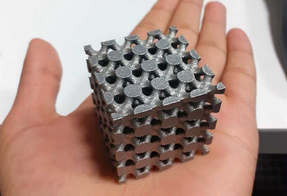
This Technology is important because it enables us to produce extremely complicated parts that we could not produce with older methods. Now we are able to make any 3d shape and we are free to optimize for ultra-high performances (ex, topological optimization). It is fast and reliable for less number and special shapes but not very useful for mass production (yet).
AM is also an efficient option for rapid prototyping. It is cost-effective and fast for making prototypes and comparing designs in real-life scenarios. This is a very important step in the testing phase of the state of the art products.
what are additive manufacturing steps?
Production with AM technology has some steps that I am going to list here. The steps are almost the same for all process types in this category. later I will discuss each step in detail with a real-world example.
- Designing the CAD file (3D model) of the part
- Conversion of the CAD to STL file format
- Preparing and Repairing the STL file
- Orientating the part and support generation
- Slicing the model (dividing into layers)
- Check the Slices for errors
- Set process parameters (specific to process type)
- execute the operation in the machine
- Post-processing (removing supports, post-curing for SLM, … etc)
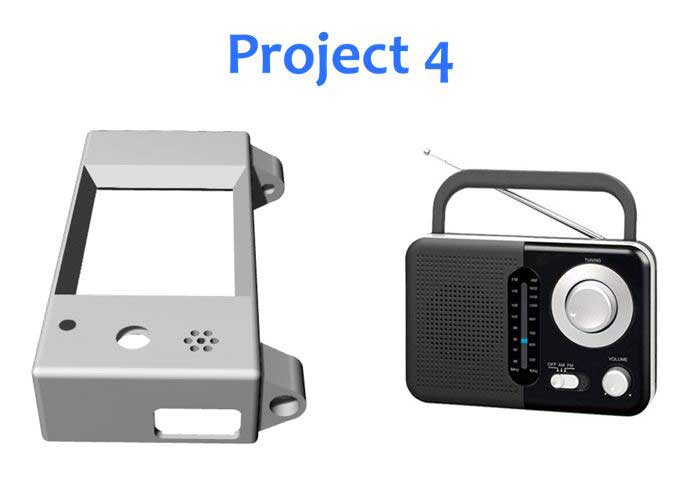
The project
Plan the fabrication process of the assigned component by employing the main 4 AM technologies. (Stereolithography, Selective Laser Melting, Fused Deposition Modeling, and Laminated object manufacturing)
Project Requirements:
- Obtain minimum roughness in the holes
- The number of components to produce in the machine is 15
- Minimize using of support material
- Calculate process time
All good, we have the Model In STL format so Lets begin! 🙂
1-2. Designing 3D Model and conversion to STL Format
This is the first step to make a product, whether you want to manufacture it with old methods or with additive manufacturing. You can use different software. Well-known software in the CAD field are Catia, SolidWorks, SolidEdge, or others. Since this article is not about modeling and the model for our project is provided by profs, I will pass this point quickly.
3. Preparing and repairing the STL File
STL file conversion is not optimal due to multiple reasons. Algorithms that are used by CAD software are not 100% optimal and they create errors when converting files to STL. Therefore we need to check and repair files before continuing to other steps. To accomplish this, we use NetFabb by Autodesk corporation. Please note that this is commercial software but it offers a free version for students. Another free alternative for Netfabb is Meshmixer also from Autodesk corp. This is free to use, but limited software good for hobbyists and not suitable for industrial use.
Netfabb has many tools and algorithms to repair STL files and perform other operations that we will see later.
Missing surfaces are colored in red, So we can use various tools to correct the part. Automatic correction is also available but not recommended. For more details on repairing STL files read my article about HOW TO REPAIR A STL MODEL WITH NETFABB 2020
4. Orientating and support generation
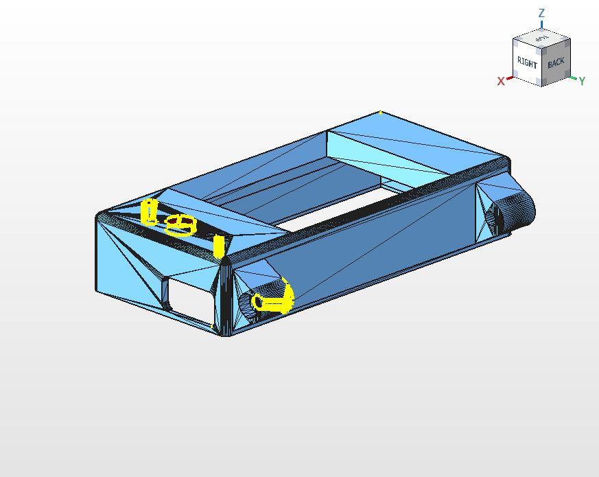
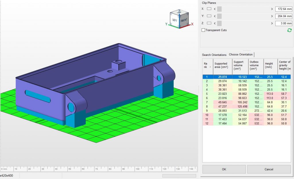
Netfabb suggests Orientations in a nice table. It provides different suggestions and calculates the amount of support material required for each orientation. (see Figure 3). In the table on the right side, the software chooses the best orientation but also gives you the opportunity to alter its choice according to your preferences. Orientation is very important for the optimization of the amount of support material to be used and surface roughness of different regions because of the staircase effect (Only in FDM).
We have to choose an optimal orientation to comply with our surface roughness requirement as well as support material minimization. The software does not consider surface roughness and its suggestion is mostly based on support volume. With this orientation (see figure 3), we will have minimum roughness on sidewalls but our requirement is to obtain it on the surfaces of the holes. we will have the least support material used in this orientation.
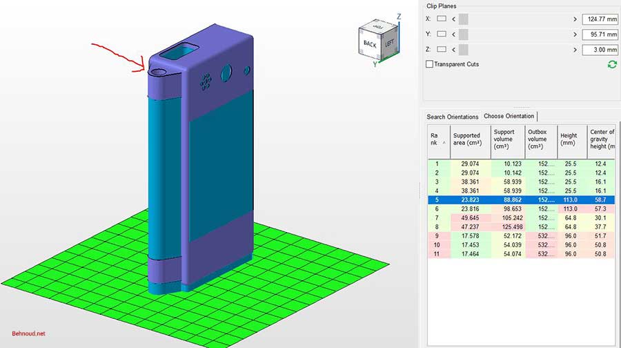
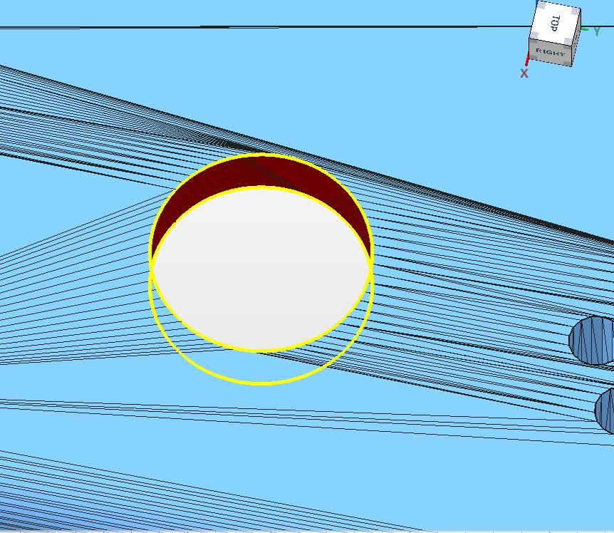
I highlighted the holes that we need to have the best surface roughness. With this orientation, I can achieve the best possible surface roughness for both of holes. On the other hand, we will use more support material. After choosing the orientation and generating support, we will go to the next step which is Slicing.
5. Slicing
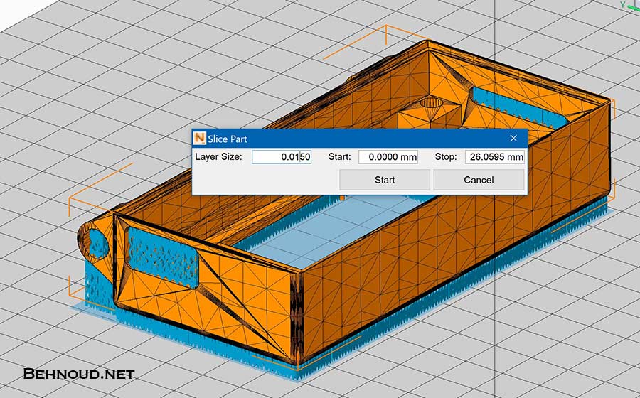
Slicing is a very important step in any additive manufacturing process. You need to define a suitable layer thickness and perform slicing. It is mostly dictated by the machine and process. Most SLM machines have a fixed layer thickness parameter but in FDM you have more freedom to adjust.
Let’s perform slicing on our model and see how many layers we need to create in the actual process.
In Netfabb you can choose the most popular additive manufacturing machines. EOS, HP, Makerbot, MarkForged, and many more are available. With this useful feature, you can choose your machine and their bed size and other parameters will be automatically applied to the environment. After slicing, you can simulate the tool path and layer by layer construction.
6- Slicing check
In the Slicing visualization tab, you can observe the tool path and also check for closed vertices in 2d demonstration. The program will warn you of open vertices and other probable errors. For more information on slicing and exporting slices file see this video tutorial.
7- Set the process parameters
Parameters are closely related to the type of process (SLM, SLA, FDM, LOM, …) and the machine that you are using. Here I will mention parameters for each technology.
SLM process parameters are :
- Laser Power
(Usually constant and machine-dependent) - Scanning speed
(We need to choose) - Layer Thickness
(Usually constant and machine-dependent) - Hatching distance
(We need to choose)
FDM process parameters are :
- Layer thickness
(ranges between 0.127 – 0.331 mm) - Deposition speed
(Machine dependent) - The temperature on deposition head and room
8- Physical fabrication
Finally, you are ready to send the slices file to the machine and adjust the parameters and execute the operation.
9- Post processing
After finishing the production, You need to remove supports, apply surface finishing, or put the SLA part in a UV oven for post-curing. This is a crucial step for obtaining a high-quality part.
Read more
Read a recent article about the usage of additive manufacturing for making high-performance, low-weight car parts by Porsche in this link.
That’s all!
Hopefully, you have a general understanding of how additive manufacturing works!
If you find any errors or if you have any suggestions, please let me know in the comments section below.
Thanks
Please share this article:
Post a comment:
😃 Be the first to write your Idea ...